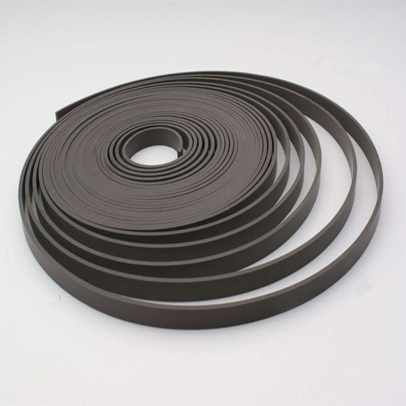
Novenco Bronze Filled Wear Strip Roll
Our Bronze Filled PTFE compound provides great light-duty, low friction performance.

NEC - 07
NOVENCO produces, Tight Tolerance, PTFE Bearing Tape that is designed to eliminate scoring in Hydraulic and pneumatic cylinder applications by preventing metal to metal contact. Our Bronze Filled PTFE compound provides great light-duty, low friction performance.
NOVENCO possesses the expertise to make the best quality skived PTFE products in the market today. Precision crafted in to rolls; our Bearing Tapes are made with the latest skiving. Technologies and premium selection of Raw materials. Our Bearing Tapes can be produced from 0.063' up to 0.125' thick (from 1.5 to 4mm), in widths from 0.25' upto2' (from 3 to 49.8mm).
The process of ordering is very simple- just select a Thickness (C/S) and the Width (L2). Don't forget to double check your Groove Width for clearance (L1). The roll length will be determined by the Thickness(C/S).
| OPERATING CONDITIONS | METRIC | INCH |
|---|---|---|
| Maximum Speed | 5.0 m/Sec | 16 ft/Sec |
| Temperature Range | -50°C +200°C | 58°F +390°F |
| TYPICAL PHYSICAL PROPERTIES | METRIC | INCH |
|---|---|---|
| Specific Gravity | 3.1 | 3.1 |
| Compression Stress at Yield | 20 MN/m² @ 23°C | 2900 psi @ 73°F |
| Compression Stress at Yield | 9 MN/m² @ 80°C | 1300 psi @ 176°F |
| Coefficient of Thermal Conductivity | 2.5 W/mK | 1.4 Btu/hft°F |
| Coefficient of Thermal Expansion - Length & Thickness | 6.5 x 10⁻⁵ per °C | 3.6 x 10⁻⁵ per °F |
| Coefficient of Dynamic Friction on Steel Surface (0.2 μmRa) / (8 μinCLA) | Dry 0.25 | Dry 0.25 |
| Lubricated 0.05 | Lubricated 0.05 |
Note: Novenco recommends applying a 4:1 factor of safety when using the compressive stress at yield in your bearing NOTE load calculation.
| HOUSING DETAILS & TOLERANCES | ||
|---|---|---|
| Rod | Ød₁ mm | f9 |
| ØD₂ = Ød₁ + 2S mm | ≤ Ø80 H10 > Ø80 H9 | |
| ØD₃ = Ød₁ + G mm | G min / max | |
| L₁ mm | +0.20 -0 | |
| Piston | ØD₁ mm | H11 |
| Ød₂ = ØD₁ - 2S mm | h8 | |
| Ød₃ = ØD₁ - G mm | G min / max | |
| L₁ mm | +0.20 -0 |
Note: G min controls the minimum metal-to-metal clearance between the gland and rod or between bore and piston. G max controls the maximum extrusion gap seen by a seal associated with the bearing. Typically, G min should be 0.70 mm (0.0280 in) but can be reduced when required by the extrusion gap for the seal and the build-up of tolerances. The absolute minimum metal-to-metal clearance recommended is 0.10 mm (0.004 in). More information can be found in the Housing Designs and Extrusion Gaps pages at the front of the catalogue. For applications not using a seal G max, see part number range in the following pages
| SURFACE ROUGHNESS | µmRa | µmRz | µmRt | µinRa | µinRz | µinRt |
|---|---|---|---|---|---|---|
| Dynamic Sealing Face Ød₁, ØD₁ | 0.4 | 1.6 max | 4 max | 16 | 63 max | 157 max |
| Static Sealing Face ØD₂, L₁, Ød₂ | 3.2 max | 10 max | 16 max | 125 max | 394 max | 630 max |
| Thickness (C/S) | Roll Length |
|---|---|
| -0.0013 | |
| 0.063” | 40 MTR |
| 0.094” | 25 MTR |
| 0.125” | 20 MTR |
| Width (L2) | Groove (L1) |
|---|---|
| +.0007-.010 | +.0207-.000 |
| 0.250' | 0.260' |
| 0.375' | 0.385' |
| 0.500' | 0.510' |
| 0.625' | 0.635' |
| 0.750' | 0.760' |
| 1.000' | 1.010' |
| 1.250' | 1.260' |
| 1.500' | 1.510' |
| 1.750' | 1.760' |
| 2.000' | 2.010' |
| Thickness (C/S) | Roll Length |
|---|---|
| 0.01-0.05 | |
| 1.5 | 40 MTR |
| 1.6 | 40 MTR |
| 2 | 35 MTR |
| 2.5 | 25 MTR |
| 3 | 20 MTR |
| 3.17 | 18 MTR |
| up to 10 mm |
| Width (L2) | Groove (L1) |
|---|---|
| 0.01-0.20 | 0.525-0.00 |
| 3 | 3.2 |
| 3.8 | 4 |
| 5.4 | 5.6 |
| 5.6 | 5.8 |
| 6 | 6.25 |
| 8 | 8.25 |
| 9.5 | 9.75 |
| 9.7 | 10 |
| 10 | 10.5 |
| 11.8 | 12 |
| 12.7 | 13 |
| 14.5 | 15 |
| 14.8 | 15 |
| 15 | 15.5 |
| 19.5 | 20 |
| 19.8 | 20 |
| 20 | 20.5 |
| 24.5 | 25 |
| 24.8 | 25 |
| 25 | 25.5 |
| 29.5 | 30 |
| 30 | 30.5 |
| 34.8 | 35 |
| 49.5 | 50 |
| 50 | 50.5 |
| up to 100 mm | Accordingly |
The data provided is based on laboratory testing and is proposed to technical designers as possible and useful advice. Deviations from the values in di cated may occur, but they do not constitute themselves either detriment of quality or reason for rejection.