Novenco FRPR Wear Strip Roll + Fine PTFE Molecules
support horizontal loads and prevent metal-to-metal contact of moving parts


NEC - 01-PT
The role of the wear ring is to guide the piston and the rod in a hydraulic cylinder as well as to support horizontal loads and prevent metal-to-metal contact of moving parts.
CHARACTERISTIC OF WEAR RING
Design of Wear Ring
Calculation of the cutting gap for Wear Strip The length of Wear strip would be calculated by following :
For Pistons
L = (D - W) × 3.092
L: Max. Wear ring length
D: Cylinder Diameter (OD of wear ring)
W: Thickness of wear ring
For Rods
L = (D + W) × 3.092
L: Max. Wear ring length
D: Rod Diameter
W: Thickness of wear ring
Strip Type: Cutting gap = 1.4mm
Standard cutting gap & type of cutting for Wear Ring : Bias cut is a standard cutting type. Step cut can be used as a buffer seal by protecting seals from pressure spike. The other type of cutting would be available as per customer request. Table 1. Shows the Standard cutting gap and Figure 1 shows the type of cutting.
| O.D. of Wear ring | Cutting(Z) |
|---|---|
| ØD 25 | 1.0mm |
| 26 Ø 100 | 2.0mm |
| ØD 101 | 2.5mm |
| Properties | Units | Grades | ||
|---|---|---|---|---|
| NEC 01-PT | ||||
| Comprehensive Strength |
At Failure (Temp.23oC) |
MN/m2 | 425 | |
|
At Yield (Temp.23oC) |
MN/m2 | 108 | ||
| Comprehensive Strength |
At Yield (Temp.23oC) |
MN/m2 | 80 | |
| Shear Strength | MPA | 80 | ||
| Hardness | Rockwell | HRM | 100 | |
| Material Swell in Water (% wall thickness) | % | 0.08 | ||
| Maximum Sliding Speed | m/s | 2.0 | ||
| Temprature | Maximum | oC | 120 | |
| Maximum | oC | -40 | ||
| Coefficient of linear thermal expansion | Normal to laminate | 10-5/oC | 7 ~ 8 | |
| Parallel to laminate | 10-5/oC | 5 ~ 6 | ||
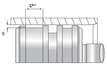
Guide elements can be easily mounted in closed grooves in accordance with ISO 10766. Guide strips NEC 08, NEC 01 and NEC 07 must be cut to length so that clearance is available for the joint.
The following formulas are used to determine the stretched length L1
- Piston Guide Ring L1 = 3,11 x (ØD-S) - 1,0
- Rod Guide Ring L1 = 3,11 x (Ød+S) - 1,0
Possible cut forms:
- 30o = better pressing force distribution and
ease of mounting
- 90o = and ease of mounting

- ST = rotation/oscillation

Media Resistance
- Hydraulic oils in accordance with DIN 51524 section 1-3
- Petroleum-oil based-lubricating oils, greases
- Flame retardant hydraulic fluids HFA, HFB, and HFC inaccordance with VDMA 243170,2d


Dimensions
NEC 01-PT
| WIDTH (mm) | THICKNESS (mm) | |||||||
|---|---|---|---|---|---|---|---|---|
| 5.6 | 2 | 2.5 | 3 | 3.5 | 4 | 4.5 | 5 | 6 |
| 8 | 2 | 2.5 | 3 | 3.5 | 4 | 4.5 | 5 | 6 |
| 9.5 | 2 | 2.5 | 3 | 3.5 | 4 | 4.5 | 5 | 6 |
| 9.7 | 2 | 2.5 | 3 | 3.5 | 4 | 4.5 | 5 | 6 |
| 12.5 | 2 | 2.5 | 3 | 3.5 | 4 | 4.5 | 5 | 6 |
| 14.8 | 2 | 2.5 | 3 | 3.5 | 4 | 4.5 | 5 | 6 |
| 15 | 2 | 2.5 | 3 | 3.5 | 4 | 4.5 | 5 | 6 |
| 16.3 | 2 | 2.5 | 3 | 3.5 | 4 | 4.5 | 5 | 6 |
| 16.5 | 2 | 2.5 | 3 | 3.5 | 4 | 4.5 | 5 | 6 |
| 19.5 | 2 | 2.5 | 3 | 3.5 | 4 | 4.5 | 5 | 6 |
| 20 | 2 | 2.5 | 3 | 3.5 | 4 | 4.5 | 5 | 6 |
| 24.5 | 2 | 2.5 | 3 | 3.5 | 4 | 4.5 | 5 | 6 |
| 25 | 2 | 2.5 | 3 | 3.5 | 4 | 4.5 | 5 | 6 |
| 29.5 | 2 | 2.5 | 3 | 3.5 | 4 | 4.5 | 5 | 6 |
| 30 | 2 | 2.5 | 3 | 3.5 | 4 | 4.5 | 5 | 6 |
| 35 | 2 | 2.5 | 3 | 3.5 | 4 | 4.5 | 5 | 6 |
| 40 | 2 | 2.5 | 3 | 3.5 | 4 | 4.5 | 5 | 6 |